Field note · updated 5 November 2026
It gets warm. Where the heat is — and what we did about it.
The short answer
The heat is not spread evenly across the board. It concentrates in three places: the system-on-chip in the middle, the power conversion section, and the memory area around them. A blower in the middle blowing outwards across both sides of the board is the shape that follows that. A blower aimed only at one edge, which is what most printed brackets do, moves air along the board instead of across it.
If you are going to power a fan, the pad that people tap on these boards is a 3.3 V rail shared with the system, not 5 V. That is what we used: an 18 × 18 × 4 mm blower rated 0.1 W, which on that rail is roughly thirty milliamps of arithmetic, not a measurement. It spins up before the system boots, and it needs nothing but two wires — no driver board, no fan header.
All of it comes from one board we took apart and ran: our own V30, an infrared camera pointed at it while it worked, and the parts we fitted. The photographs and the film below are that unit.
0. The build, in two minutes
The whole mod, from opening the back to the second airflow test. It is a portrait clip with the narration burned in, and the same words are attached as captions, so it plays without sound if that is easier.
- 0:00Open the back
- 0:09The battery is 11.1 Wh, and that decides the fan
- 0:15An 18 × 18 × 4 mm blower, 0.1 W
- 0:22Two centimetres of clearance, then sand the edge
- 0:29The V30 heat map, after running
- 0:34The module beside the speaker
- 0:37Three heat sources, not one
- 0:43Air in on the left, out on the right
- 0:493.3 V from the flash rail
- 0:53The solder layout
- 0:56Power-on check, before the system boots
- 1:13Thermal pad, heatsink, fan
- 1:18It moves a pen
- 1:27A vent on each side
- 1:33A groove about 3 mm deep
- 1:41Snap it with pliers
- 1:51Nine holes for intake
- 1:58Test the airflow again
The same build is also posted on X ↗ with the photos in a single thread.
Before any of this: disconnect the battery. Every step from section 5 onward happens with the shell open and a soldering iron or a drill near a board that is otherwise live — the cell comes out of its connector first, and only goes back in for the power-on check.
1. Opening it, and the one number that decides the rest
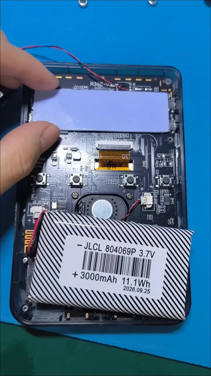
The back cover comes off with the screws out and the battery sits in the lower half with its connector on the board edge. Nothing is glued and nothing is clipped in a way that breaks on the first opening.
The number to read first is on the cell: 11.1 Wh — 3.7 V at 3000 mAh on our unit. It is what decides the fan choice, because the fan is going to run for the same hours the handheld does. A blower that draws tens of milliamps against an 11.1 Wh cell costs a few percent of runtime; one of the 5 V fans people fit with a boost converter costs considerably more, and it needs that converter in the first place.
2. Sizing the fan before cutting anything
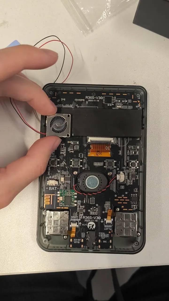
The part we used is an 18 × 18 × 4 mm blower, rated 0.1 W. It is small on purpose: the space between the board and the back cover is thin, and a bigger frame buys airflow the shell cannot deliver.
Before it goes anywhere near the shell, hold the fan and the heatsink against the board at the place they will live and check the clearance — on our unit the assembly wants at least two centimetres of depth. Then sand the cut edge flat, because a rough edge becomes a gap and a gap is where the air leaves without crossing anything hot.
3. Where the heat is, from the camera
We ran the board with the shell off and an infrared camera on it, and marked the regions that matter. The frame below is what the build is designed against.
The system-on-chip is the hottest single point. It is the large square in the middle of the board, and it reads highest in the image — 48.0 °C at the surface, with the surrounding board a little cooler.
The power conversion section is second. This is the cluster of inductors and switching regulators at one side of the board. It is not a chip you can stick a heatsink on in the usual way, it is spread over an area, and it is the part most printed cooling brackets miss entirely.
The area above the battery reads warm too — 45.8 °C on the lower marker, and it is the broadest of the marked regions for a fan to move air over.
The camera marks four points and not the memory packages, so this article does not put a number on the memory. What the frame establishes is where the readings are highest; the narration in the film names the memory area, the SoC and the power delivery as the cluster, at the scale a 18 mm fan cares about.
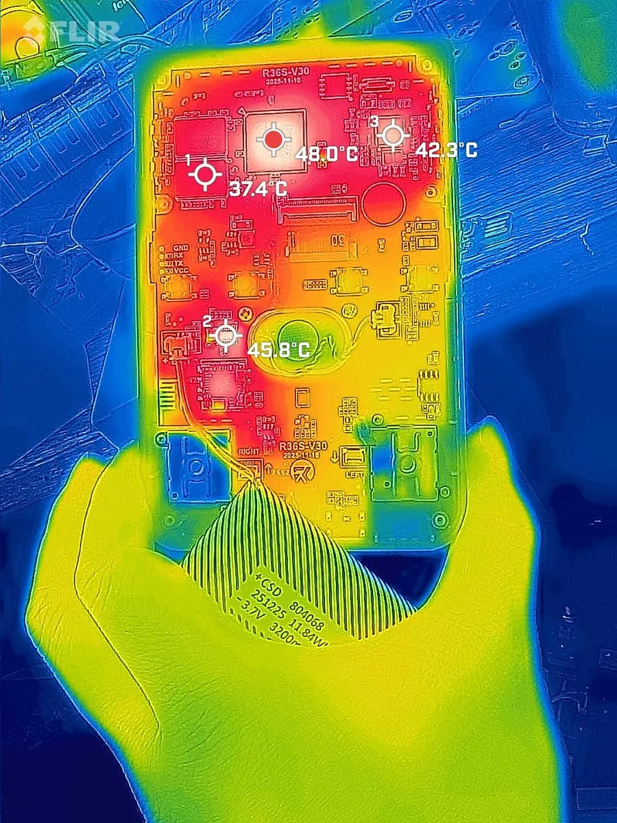
Two things about that reading. It is a surface temperature with the back cover off, so the shell an owner touches is always cooler than these numbers. And it is one frame, not a curve — what it establishes is where the heat is, not how hot the unit gets after three hours.
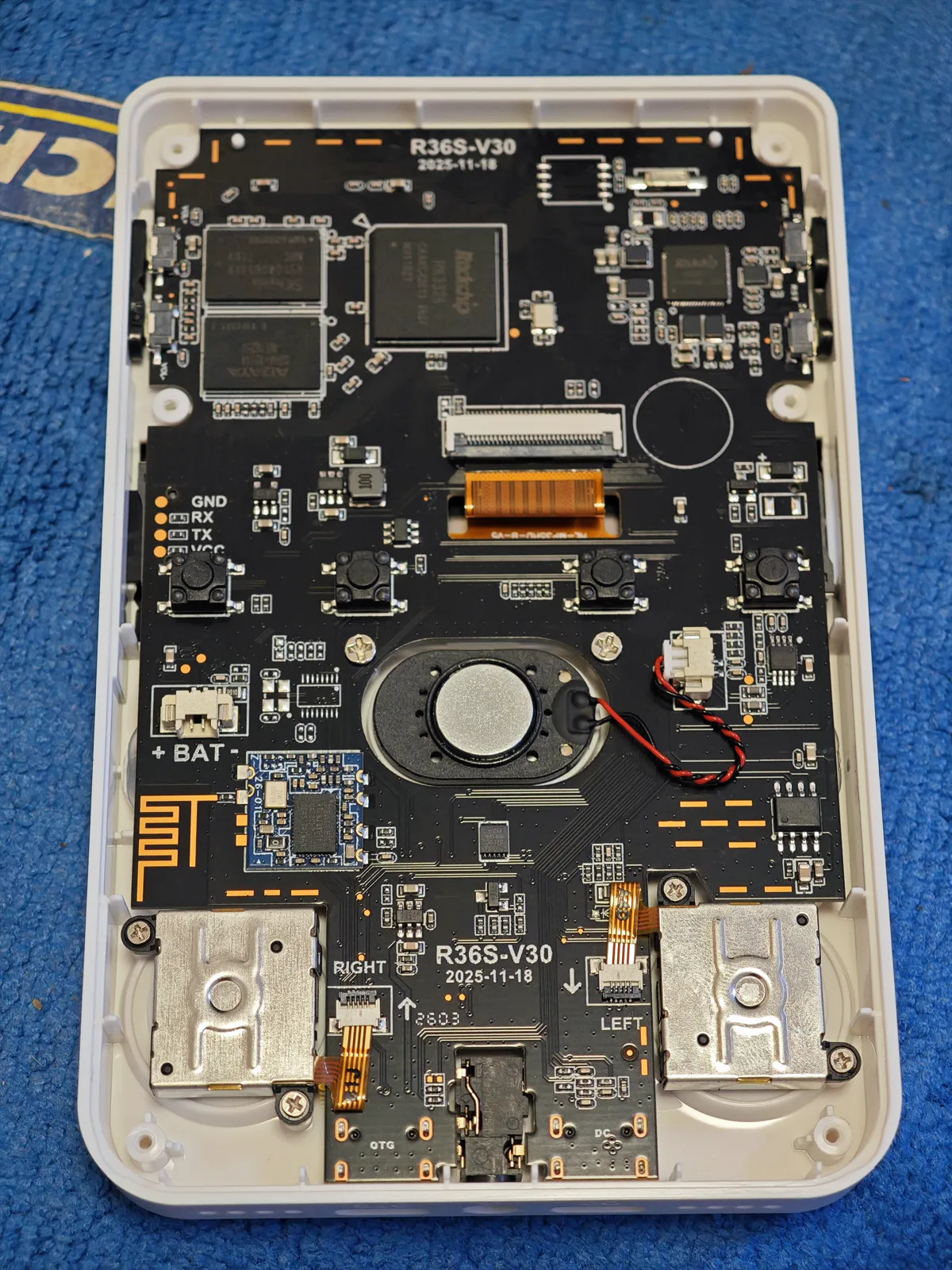
One region is out of reach of any fan: the module beside the speaker. It sits against the shell in a corner the airstream cannot cross, so no amount of printing puts air on it. That is a limit of the layout, not of the mod.
4. Left in, right out
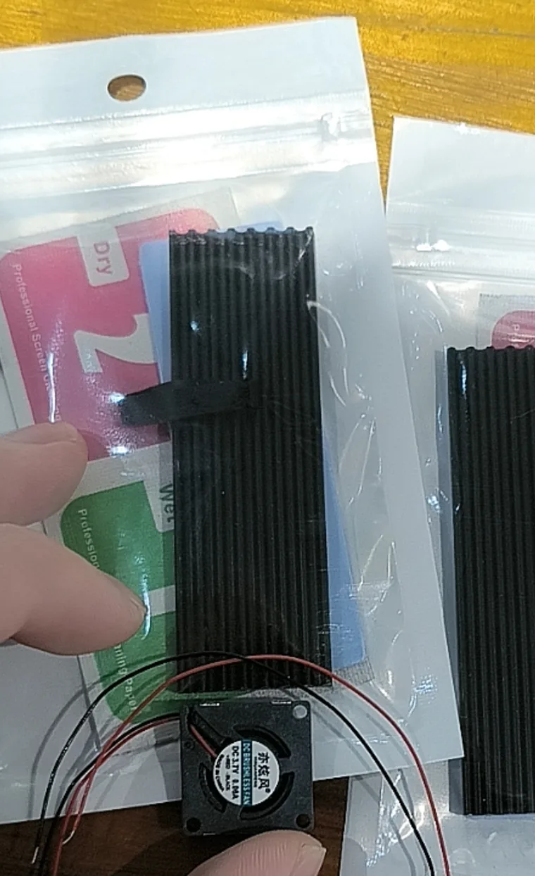
Two details matter more than fan size.
Placement and direction. The blower goes at one end and pushes air across the board to the other, so a single airstream crosses the chip and the power section on its way out. On this build that is left to right, with the intake on the left edge and the exhaust on the right. A blower at one edge pulling air across the whole length of the board is the same idea done the wrong way round — the part nearest the fan gets the cool air and everything downstream gets pre-warmed air.
A heatsink under the fan. Air moving over a bare chip does relatively little. A small aluminium heatsink bonded to the system-on-chip, with the fan over it, is where most of the gain comes from. The flat M.2-sized plates sold for SSD cooling are the usual donor — they are thin, they come with thermal pads, and one of them is roughly the right footprint.
5. Tapping 3.3 V from the flash rail
The obvious thing to do is find a 5 V pad and run the blower from it. On these boards that pad is usually not 5 V.
The pad people tap for this on the flash area carries 3.3 V, and that rail is shared with the running system rather than dedicated to accessories. It is also live the moment the cell is connected, which is why the fan starts before the operating system does — useful, and a reason to be careful.
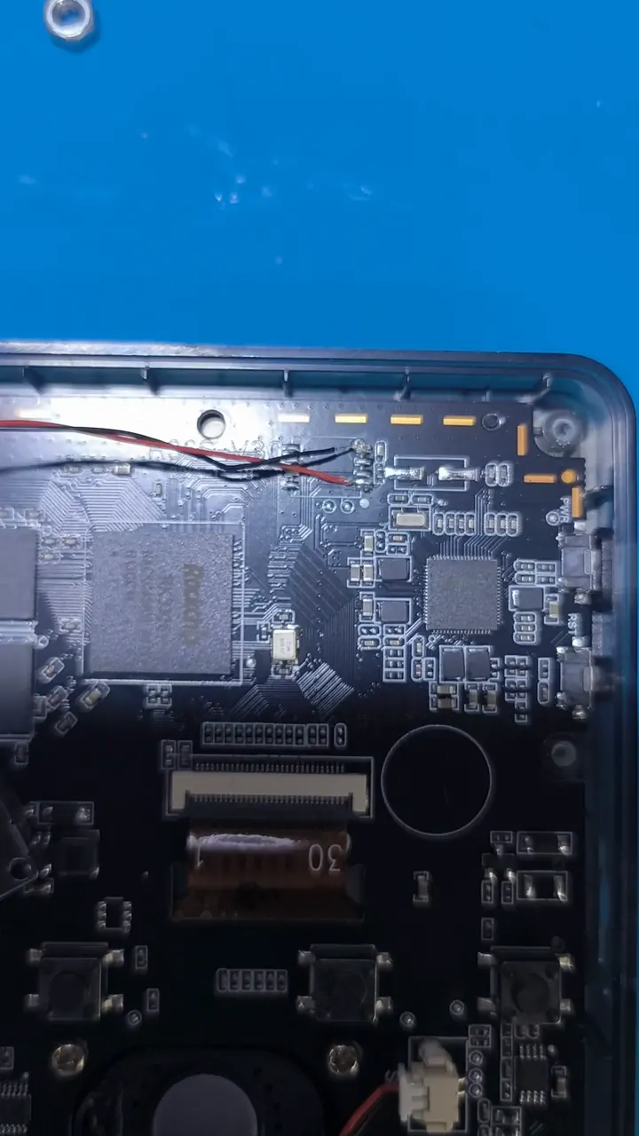
Two consequences follow. A 5 V blower will spin on it, but at roughly two thirds of its rated speed and with much lower starting torque — which is why a 0.1 W part is the right choice here rather than a bigger one that would stall. And whatever you pull comes out of the same budget the rest of the board is using, so the draw has to stay small. Thirty milliamps or so is where this build sits.
Disconnect the cell before you solder. Put a meter on the pad and confirm the voltage on your own unit before attaching anything — the rail is shared with the running system, so a mistake on it is not a mistake in a fan circuit, it is a dead handheld. Work with a fine tip, and if you have not soldered before, this is not the project to learn on.
Then reconnect the battery and power the unit on: if the fan spins before the system boots, the tap is correct. Ours did, and that is the whole electrical check.
6. Pad, heatsink, fan, and a pen
With the electrics proven, the mechanical part is short. Thermal pad on the chip, heatsink on the pad, blower on the heatsink, and the wires routed so nothing is pinched when the shell closes.
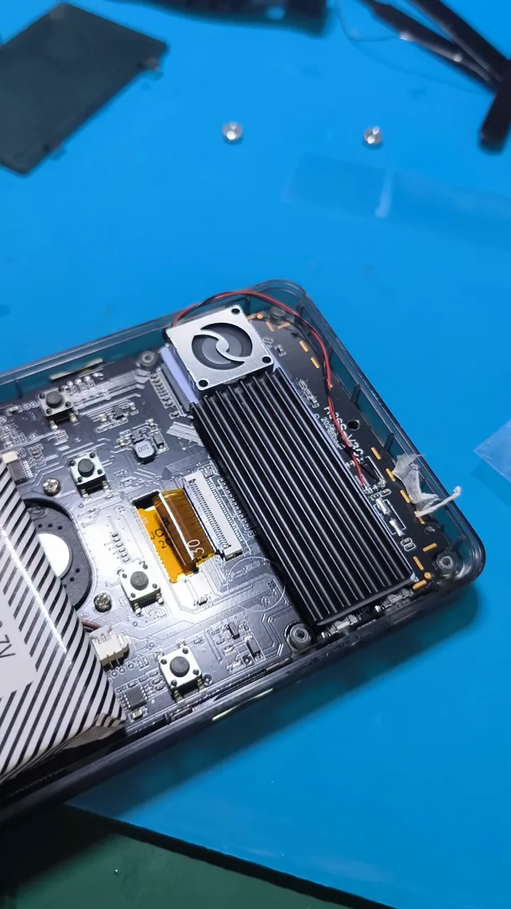
The airflow test is deliberately crude: hold something light next to the exhaust and see whether it moves. A pen on a bench is not a flow meter, and we are not going to pretend it is — what it establishes is that the fan is pushing air in the direction the design intended, which is the thing that could be wrong at this stage. Ours moved the pen.
7. Cutting the shell
A fan inside a closed shell just moves the same warm air around. It needs a way in and a way out, and they belong on opposite sides.
Mark before cutting. Score a groove about 3 mm deep along the vent outline and draw the cut line at its deepest point, so the tool has a track to follow rather than a freehand edge to wander off.
Snap, don't saw. The shell is ABS, and ABS is tough: flex the piece along the groove with pliers and it breaks cleanly at the line. It is also the step where an over-confident pull cracks the shell in the wrong direction, so work slowly around the perimeter.
One more intake, nine holes. The second opening was drilled rather than cut — nine holes in a grid, aimed with a drill press or a guide so the bit does not skate across the plastic.
Do the shell work with the board out. Plastic chips are conductive enough to matter and they get everywhere.
8. The second test, and what we have not measured
The finished unit got the same pen test as the bench assembly, and the airflow still moves it with the shell closed and the vents in place. That is where the film ends, and where the honest part of this article starts.
We have not measured the temperature delta. No before-and-after curve, no soak test, no reading taken with the shell on. The mod exists, it runs, and the air goes where it was aimed — but nothing on this page says the chip is now N degrees cooler, because we have not measured it. That is the next thing to do, along with the overclock question the film raises and does not answer.
What follows from the work rather than from a measurement: the mod is not reversible in the ordinary sense. Solder and a hole in the shell are permanent. A printed bracket can be taken off and a different one tried; an 18 mm hole cannot.
The warranty. Opening the shell and soldering to the board ends any support arrangement you have with whoever sold you the unit, ours included.
Dust and noise. A blower inside a plastic shell pulls air through the vents and pushes dust with it. Any unit with a fan in it needs cleaning eventually, and a small blower at close range is audible in a quiet room.
The order to do this in. Fit the heatsink and check the temperatures you have now before cutting anything. Then decide whether the fan and the two holes are worth it. Doing the shell first means a hole you cannot un-cut if the rest does not work out.
What this article is based on
One unit: our own V30 sample, opened, run under load, photographed and then modified. The temperatures in section 3 are read off the infrared frame — 48.0 °C on the system-on-chip, 42.3 °C on the power section, 45.8 °C in the lower area, 37.4 °C beside the chip. The heat map itself came from a friend in the community, who ran their board for the camera; the unit in that frame is theirs.
The build photographs and the film are of our unit and our bench. The parts are the ones in section 4: an 18 × 18 × 4 mm blower rated 0.1 W, two M.2 heatsinks, thermal pads, two wires, nine drilled holes and two cut vents.
What we did not do: a before-and-after temperature comparison, a runtime measurement with the fan fitted, a current measurement at the pad, or a long soak test. Where a number appears on this page it was read off the hardware, the camera or the arithmetic — the thirty milliamps is 0.1 W over 3.3 V, not a meter reading.
We sell these handhelds, so read section 8 as the one that argues against a sale-adjacent purchase: this mod ends the warranty on the unit you are drilling.
Related reading
V12, V21 or V30 — board revisions, and the WiFi tradeoffs that come with them.
The light is on and the number is not moving — what the charging path actually does, and why the cell does not like being left at the menu.
What games can it run? — the load that makes a unit warm in the first place.
First steps, the shop FAQ, and the bare R36S.