Field note · updated 12 November 2026
The port has no power. The board is fine.
The short answer (corrected)
Update, 12 November 2026. When this note was first published it ended with "the board is faulty, send it back". That was wrong. The same board, with the same mouse, works — after the system was replaced with a current build. The correction is below; the measurements that led us astray are still here, because they are worth understanding.
The right-hand port is a host port and must supply 5 V. On the unit we opened it supplied 1.6 V and no device was recognised. We could not find 5 V anywhere on the board, and concluded the power stage was dead.
What we missed: the rail that feeds this socket is not left on by hardware. It is a fixed regulator switched by a GPIO, declared in the device tree as vcc_host with regulator-always-on and enable-active-high. The firmware that shipped on our unit had no such node. The pin sat un-driven, the switch stayed open, and the 1.6 V we measured was leakage through the open switch — not a broken converter.
A current build declares that regulator, the kernel turns it on at boot, and the socket is live. Our unit now enumerates a USB mouse on the OTG controller. The fix is a system update, not a repair.
Everything below is still from one unit and one multimeter. Where we were wrong, we say so.
1. What the port is, before we get to what it is not
Two USB-C sockets sit on the bottom edge. The left one is the DC input — the only way this handheld charges. The right one is the OTG port. It sits next to a 3.5 mm headphone jack, and it exists so you can plug in a keyboard, a mouse, a gamepad or a USB WiFi stick.
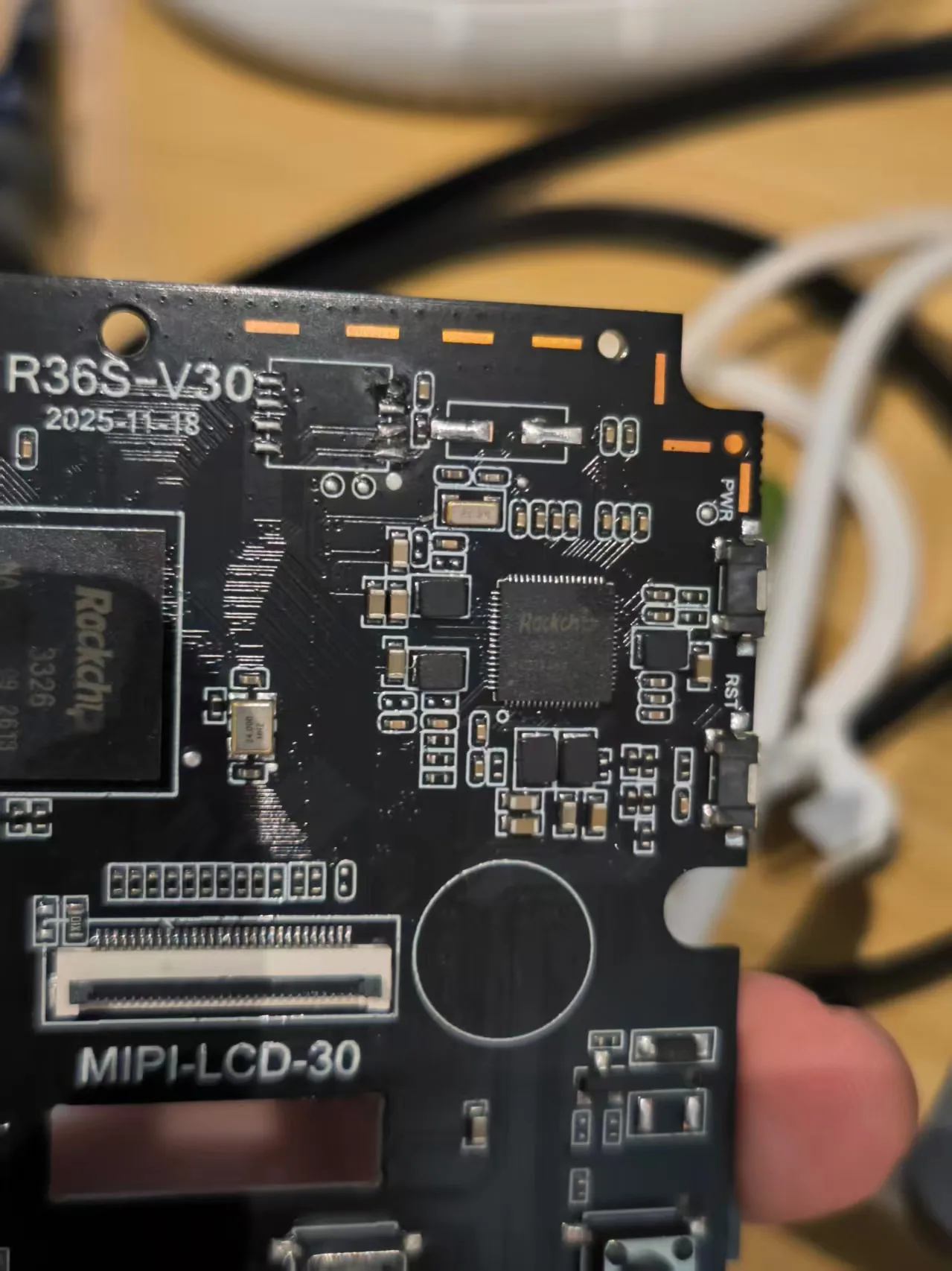
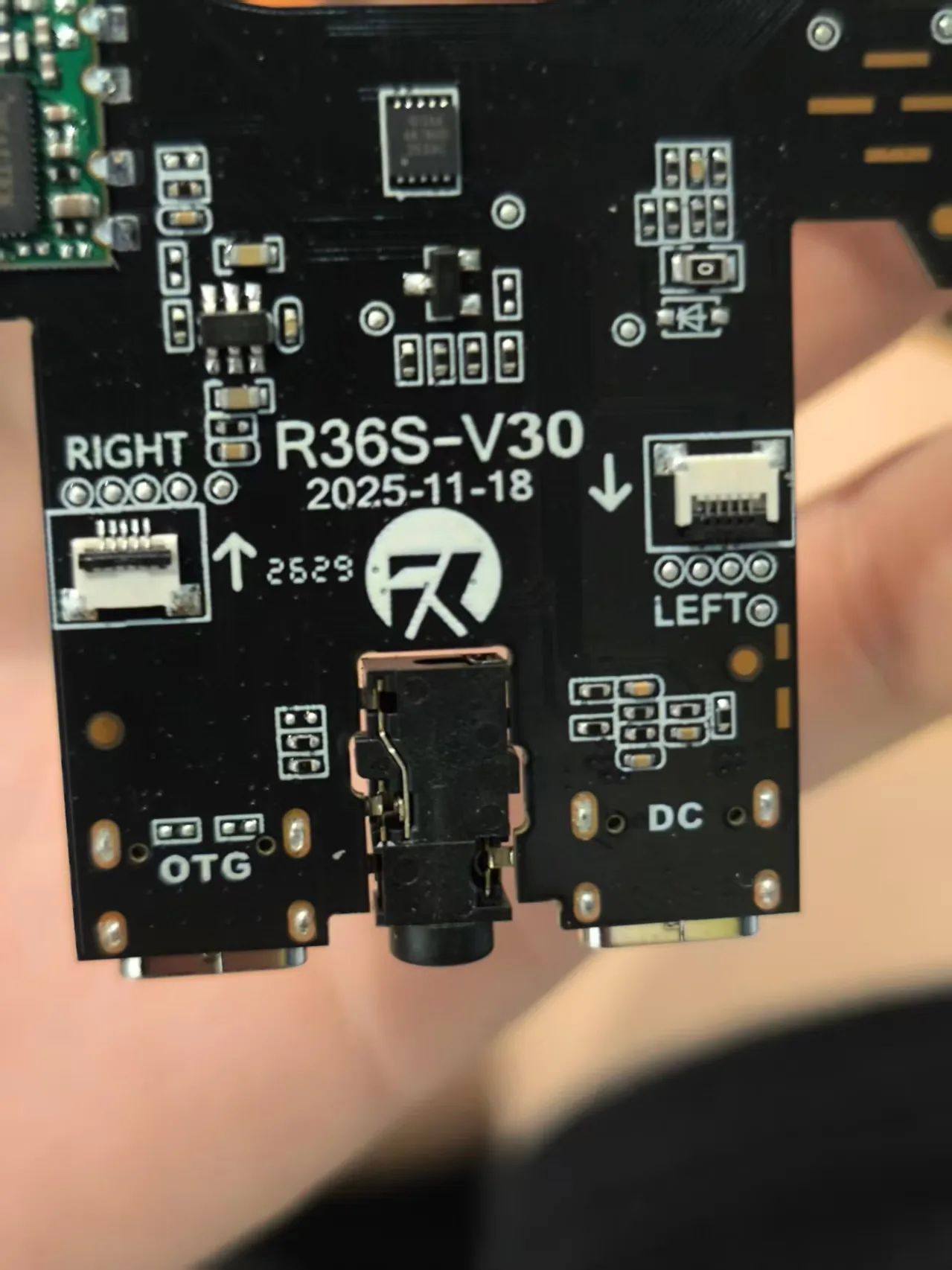
It is a host port, which has one practical consequence: plugging it into a PC does nothing. It will not appear as a flash drive, and you cannot read the card through it. That surprises people, and it is normal. The card reads fine in any card reader.
What a host port must do is simpler: supply 5 V on the power pin, and talk to whatever answers. On this unit the second half never had a chance, because the first half never happened.
2. Where the 5 V is supposed to come from
The battery sits between 3.6 and 4.2 V, so something has to raise that to 5 V for the USB port. There are two different 5 V stories on this board and it is worth separating them, because we got them mixed up at first.
The power management chip has its own OTG function. The RK817 supports a single port that both charges and discharges: with a charger attached, current flows in through a buck converter and into the battery; with OTG enabled, the same converter runs backwards as a boost. The device tree describes exactly that — a BOOST regulator specified at 5.00 to 5.40 V, marked regulator-always-on. That is the chip's own definition of OTG.
It is not what feeds the exposed OTG socket. On this board the socket's 5 V comes from a rail of its own, switched by a GPIO and left on for as long as the system is running — it feeds both the OTG socket and the internal USB hub. On a current build that rail is declared in the device tree as vcc_host: a fixed regulator, enable-active-high, regulator-always-on. Worth knowing for a second reason: a plain USB-C socket is not supposed to be live until something asks for power. This one is live from boot.
We measured the converter beside the socket. Battery voltage in, 1.6 V out — but with the switch open, that number says nothing about the converter. That was the mistake.
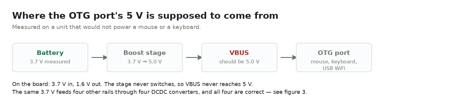
1.6 V is not a half-working converter. A converter that is switching produces its target voltage, or a ragged value under a short-circuit — it does not sit a few tenths below its own input and stay there. What we were reading is leakage: voltage arriving through a diode inside a stage that never switched on.
3. The six-pin regulator, pin by pin
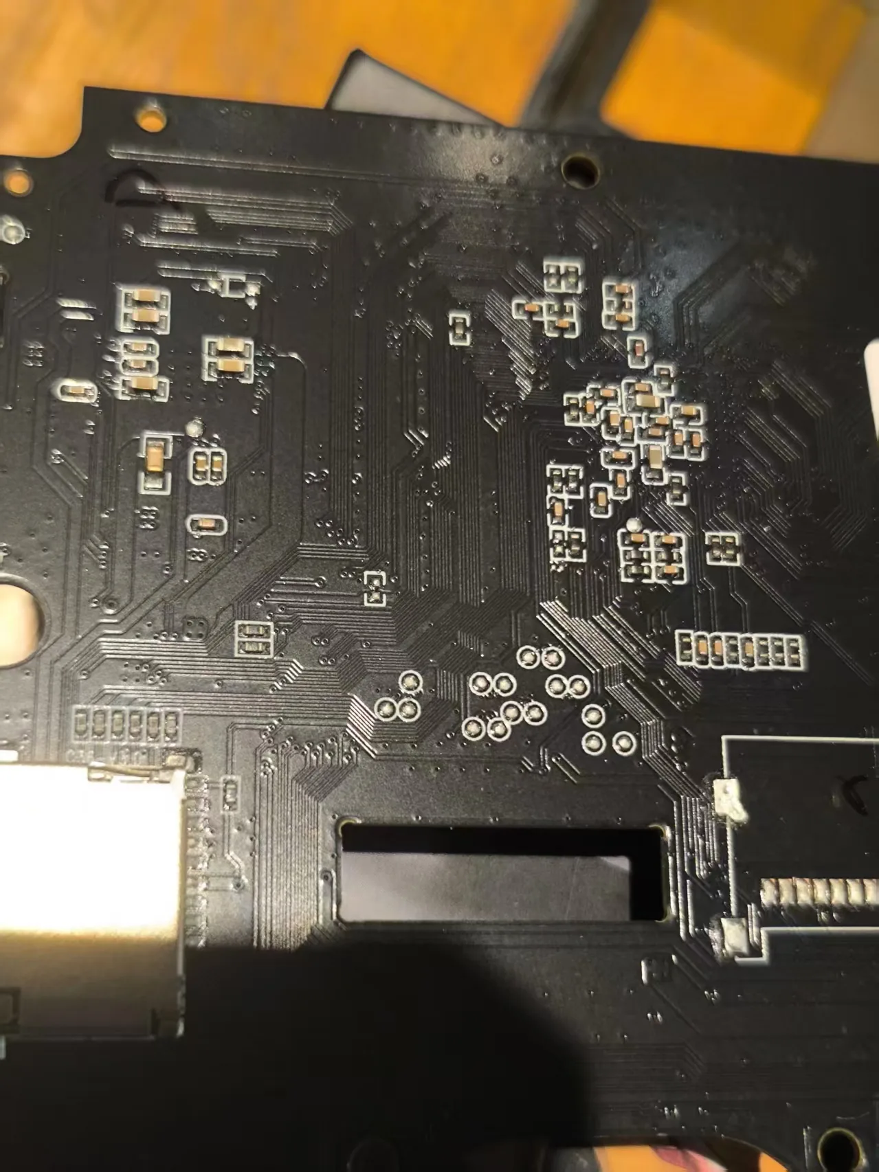
The chip beside the socket is a small SOT-23-6 package. We found its output pin first, with the meter on continuity and the unit unpowered: one pin beeped continuously against the power pin of the USB socket, which means it is wired to it directly. That established which pin should be carrying 5 V.
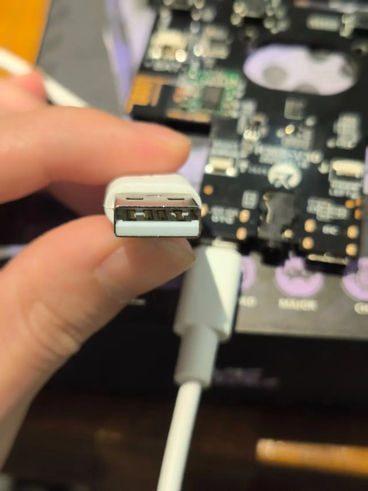
Then we powered the unit from the battery alone — no charger — and read every pin against ground.
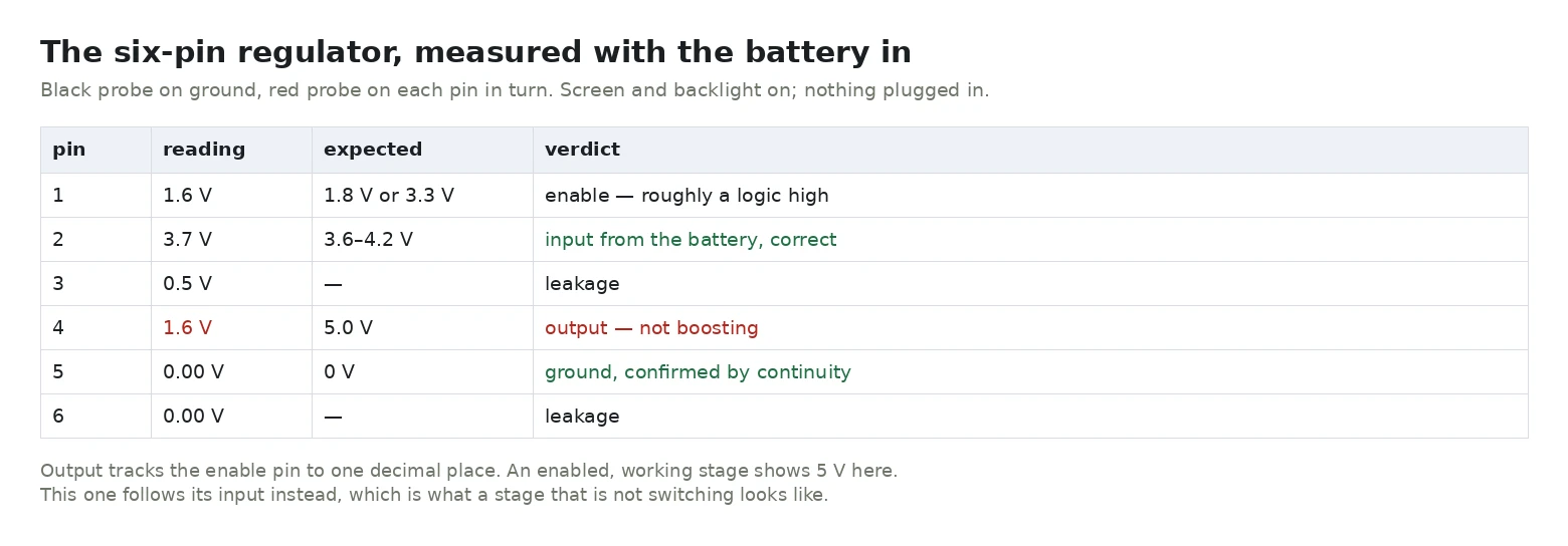
Read pin 4 against the others. It should be 5 V. It is 1.6 V — the same number as the enable pin. An output that follows its own enable signal is not regulating anything; it is passing leakage from pin to pin.
So the regulator has power, and an enable pin that is neither cleanly high nor grounded. That is the point worth stopping on. On a working board of the same revision, a second engineer measured 3.3 V on the enable pin. We measured 1.6 V. If that number is right, the converter was never properly told to turn on, and the chip may be fine.
We could not trace where the enable comes from — a pull-up, a divider, or a pin on a controller we did not identify. Nothing in the device tree drives it: we checked every regulator and every GPIO reference in the file, and no node owns this rail. So it is not something a setting can switch on, but it is also not yet proven to be a dead chip.
⚠️ Not verified: which of the two it is. A re-measurement of the enable pin, and a trace of that net, would decide between "chip not enabled" and "chip dead" — and only one of those is repairable without replacing the board.
4. All five inductors, which is the part that clears the power management chip
The five inductors around the RK817 do not feed the OTG socket — that rail comes from the separate converter above. What they do is settle a different question: whether the power management chip itself is healthy.
Inside the RK817 there are four buck converters and one boost. Each needs an inductor, and there are exactly five molded inductors around the package. We measured the far end of every one of them with the unit running.
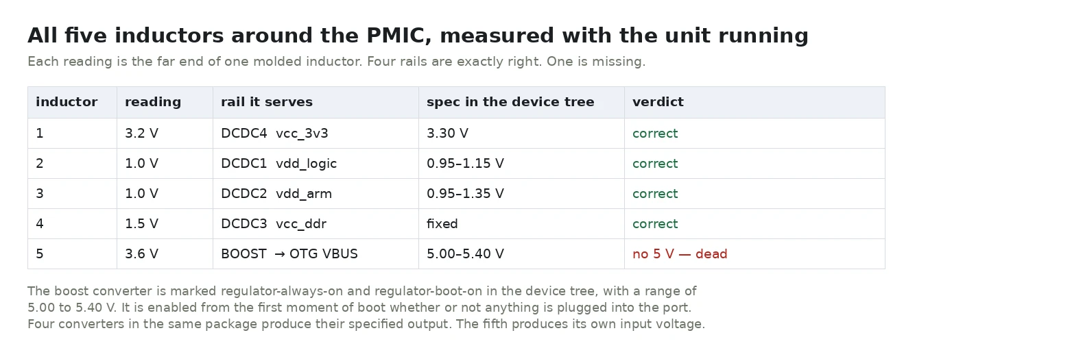
Four converters produce exactly what the device tree says they should — 3.3, 1.0, 1.0 and 1.5 V. They are not approximations; they are the specified numbers. So the package is powered, its I²C bus works, and its output stages work.
The fifth inductor sits at battery voltage, where the boost would put 5 V if it were running. That looked damning at the time. It is not — on a current build the boost is still idle and the OTG socket still works, because the socket was never fed from here.
⚠️ Lesson: a healthy-looking measurement of one subsystem told us nothing about a different subsystem that merely happened to share a symptom. We treated a coincidence as a cause.
5. We tried the software theory first, and it was wrong
The most common explanation for an OTG port that does nothing is that the USB controller is stuck in device mode instead of host mode. It is a good theory. On this unit the device tree made it look stronger than usual: the USB controller asked for one PHY port, and the same file marked that port disabled while enabling a different one that no controller pointed at.
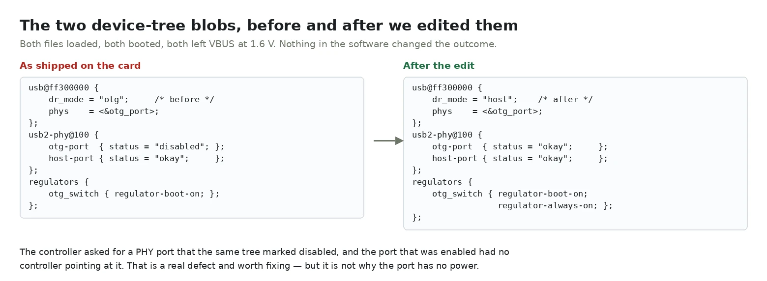
So we edited it. We flipped dr_mode from otg to host, switched the disabled PHY port to okay, and added regulator-always-on to the OTG switch regulator for good measure. The edit is small enough to be safe: otg and host are both three characters, so the binary is patched in place with no change in size.
The handheld booted normally. The screen came up, the system ran, nothing regressed. And the socket still measured 1.6 V, and the mouse still did not light.
So there is a real defect in the device tree — a controller pointing at a port the same file disables is not something to leave in place — but fixing it did not restore power. We then concluded the software theory was dead. That was the wrong inference. The theory was right; we had fixed the wrong three properties. What the file was actually missing was the regulator that switches the socket's supply on.
If you take one thing from this page: "I changed the software and nothing happened" only rules out the change you made — not software in general.
6. The WiFi, which we also got wrong
People usually arrive at this port because of WiFi, and on this unit WiFi was dead too. The first version of this page said the two were separate faults and that the OTG fix would not help. After the system update, both work — so that was wrong as well.
On the running system the USB tree settles it: an internal hub (1a40:0101) enumerates first, and behind it a Realtek 0bda:8179 802.11n adapter. The WiFi chip on this revision is a USB device on an internal hub, not the SDIO part the device tree describes. The firmware we started with had neither the driver for it nor a working host rail for the hub to sit on.
That explains why one change fixed both symptoms: the hub and the socket draw from the same rail.
7. Check your own unit — and what to do about it
You do not need to open anything. Plug a USB mouse into the right-hand port and see whether its light comes on.
Light on, device works — your port is fine. Nothing to do.
Light on, but the system does not react — power is fine and something else is wrong; that is a different investigation.
Nothing at all — before you assume the board is dead, do these in order:
- Update the system. This is the one that mattered for us. Old R36S images shipped with a device tree that declares no
vcc_hostregulator, so nothing ever switches the port's supply on. A current build does. We went from 1.6 V to a working mouse with no hardware change at all. - Unplug the charger and run on battery only. A charger can back-feed the port and hide the fault.
- Try a different adapter. Some USB-C to USB-A adapters do not tell the port to act as a host. A plain adapter and a real OTG adapter are not the same thing.
Do not send the unit back before trying an update. We nearly did, and the board was never at fault.
⚠️ Not verified: exactly which builds omit the vcc_host node, and whether every old image behaves the same way. We have one unit and one comparison.
8. What we learned from getting it wrong
We never removed a chip, never had a schematic, and never traced the enable net — and it turned out none of that was needed. The measurement was fine. The conclusion built on top of it was not.
Three things went wrong, and they are all easy to repeat:
- We measured downstream of a switch that was open. A converter that is not being asked to run reads the same as a converter that is broken. Nothing about the number itself tells you which.
- We found a real second fault and let it stand in for the first. The idle boost inductor looked like confirmation. It was a coincidence.
- We tested one software hypothesis, it failed, and we closed the category. The device tree was the answer all along — just a different node in it.
What actually fixed it: replacing the system image with a current build, which declares vcc_host. Same board, same socket, same mouse. The port we were ready to send back has been working ever since.
Related:what a device tree does and why a wrong one gives you a black screen, and the left-hand port and how charging actually works.